Geophysics HM Geophysics HM

Geophysics HM Ltd

  • Home
  • Industry
  • Applications
  • Services
  • Technology
  • Contact Us
  • Mission Statement
  • Portfolio
  • Contacts
  • Technical Team
  • Archeological
  • Bridge Inspection
  • Construction
  • Due Diligence
  • Geology
  • Environmental
  • Forensics
  • Geotechnical
  • Hydrogeological
  • Mineral Exploration
  • Road Structure
  • Utility Mapping
  • Sector Applications
  • Survey Design
  • Data Acquisition
  • Data Processing
  • Interpretation
  • Reports and Maps
  • DELTA Bridge Scanner
  • EPSILON Road Profiler
  • POISSON Time Series
  • GPR
  • Utility Locates
  • Metal Detector
  • Conductivity Mapper
  • MASW
  • Seismics
  • Induced Polarization
  • Borehole Logging
  • Geophysical Methods
  • VIC Program
  • Home
    • Mission Statement
    • Portfolio
    • Contacts
    • Technical Team
  • Industry
    • Archeological
    • Bridge Inspection
    • Construction
    • Due Diligence
    • Geology
    • Environmental
    • Forensics
    • Geotechnical
    • Hydrogeological
    • Mineral Exploration
    • Road Structure
    • Utility Mapping
    • Sector Applications
  • Applications
  • Services
    • Survey Design
    • Data Acquisition
    • Data Processing
    • Interpretation
    • Reports and Maps
  • Technology
    • DELTA Bridge Scanner
    • EPSILON Road Profiler
    • POISSON Time Series
    • GPR
    • Utility Locates
    • Metal Detector
    • Conductivity Mapper
    • MASW
    • Seismics
    • Induced Polarization
    • Borehole Logging
    • Geophysical Methods
  • Contact Us
    • VIC Program
 

ELECTRIC GRID APPLICATIONS 

Phone: (365) 889 5400

 Contact: sales@geophysicshm.com

Translate This Page

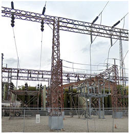
In electrical power distribution systems, a protective ground conductor is an essential part of the safety earthing system. For measurement purposes, the Earth serves as a somewhat constant potential reference against which other potentials can be measured. Knowing how to properly test an electrical ground system is essential to ensure that it has an appropriate current-carrying capability to serve as an adequate zero-voltage reference level. The main purpose of the instrument is to determine the adequacy of the grounding of an electrical system. By a standard of the National Electrical Code the resistance of the soil should be less than 25 Ohms to reliably and efficiently ground the installation. The NFPA and IEEE recommend a ground resistance value of 5 ohms or less. Computers, generating stations, and process control equipment may require as little as 1 or 2 ohms. Before the design of the grounding system begins, soil resistivity measurements need to be taken at the substation. Stations with uniform resistivity throughout the entire area are rarely found.

 Geophysical Methods Used For Electric Grid Investigations
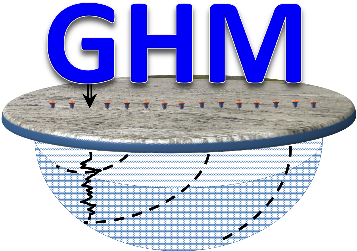
 

AEMC Tester

GPR

Utility Locates

ERT

Metal Detector

TDEM

 
Applications and Solutions
 
  • Power and Grounding Continuity Measurements
  • Ground Resistance Measurement
  • Grounding System Test
  • Ground Electrode Resistance Measurements
  • Soil Conductivity andResistivity Mapping
  • Soil Corrosivity Assessment
  • Stray Current Testing
  • Touch Potential Measurements
  • Utility Locates & Mapping
  • Buried Rod Locates
  • Grounding Mesh Test and Imaging
 
Contact Us

Geophysics HM Ltd

Geophysics HM Ltd
Tweet
 

sales@geophysicshm.com

info@geophysicshm.com

ghm@geophysicshm.com

emartinez@geophysicshm.com

Geophysics HM Ltd Office

51 Strachan Street E.  Hamilton.  Ontario. L8L3M3

Phone: (365) 889-5400

Home

Services

Applications

Technology

Contact Us

Geo Store